Installing a self-contained, wireless camera
 The Hasbro Interactive R2D2 came out in late 2002; I saw one roaming around the very first Philippine Science Fiction and Fantasy Convention at the old Louie's THX Cinema back in 2003. Since then, I knew I just had to have one. Like a lot of other people, I also saw the potential of modifying him with an internal camera.
Sometime after I got my Artoo, I bought a cheap 1.2GHz wireless camera and A/V receiver set (made in China and widely available on the Internet) that I've since successfully installed into my Interactive R2D2.

Many people on the Internet have claimed to have outfitted their Artoo units with wireless cameras. However, unlike other setups that I've seen or heard about (including a unit sold on eBay sometime ago), my R2D2's camera is completely integrated and does NOT require a separate or external battery. The whole setup is completely powered by R2's existing power system; when you turn Artoo off, the camera also shuts down.
From my own experience at A Broken Time Machine: The Fourth Annual Philippine Science Fiction and Fantasy Convention held at the Rockwell Tent on July 16, 2006, I was able to run R2 continually for more than four hours on just a single set of batteries!
WHAT CAMERA TO USE:
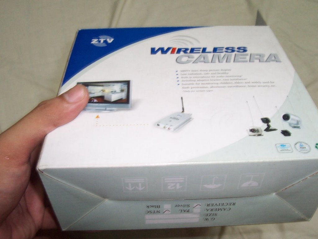
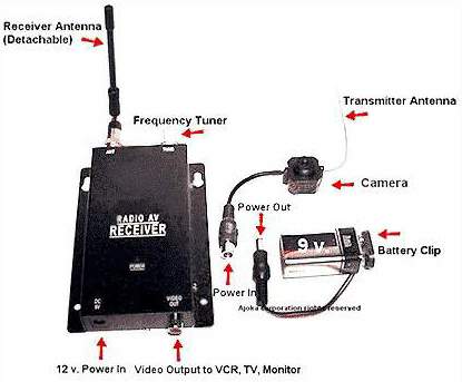 At left is a typical wireless "spycam" with the usual complement of accessories. Note that the model in the picture lacks an Audio Output jack, unlike the one that I installed in Artoo, which has complete A/V output.
The typical 1.2 GHz wireless camera is rated to 9VDC, but runs smoothly on as little as 4.5VDC. The only drawback I can see is that the camera's transmitting range is reduced. However, even at 4.5VDC, it has been successfully tested to a range of 50 feet --which, IMHO, is more than enough for R2D2 (being a voice activated toy, it's not meant to wander far away anyway).
Furthermore, Artoo's internal circuitry has clearly marked 6VDC terminals --well above the minimal power requirements for the camera. Apparently, Artoo uses the four D cell batteries to power its drive motors and uses the four AA batteries to power its sensors (more on that later in the tutorial).
TAKING HIM APART:
Taking Artoo apart for the mod is easy. There are a total of six screws that hold Artoo's front and back in place (this doesn't include the two screws that hold the battery compartment in place).
Once you have his backside off (no pun intended, hehehe) you'll find two screws that hold Artoo's head to his front half. Once you remove these, you'll have to exert a bit of force to pull the head away because of two strips of black double-sided tape (Fig04) that keep the head in place. It's inevitable that these bits of tape will get torn, but don't worry, you don't have to replace them... it's the screws that are important!
Artoo's head consists of three general parts (from top to bottom): the "dome", a red geared "plate" and a black "plate". The two plates comprise Artoo's "neck" (Fig06).
To facilitate removing Artoo's head, you should disconnect the two ribbon cables that connect from the head to the board located on Artoo's backside. Remember to take note of the positioning and alignment of these two cables!! If you mix them up during reassembly, Artoo won't function.
Next, to access the inside of Artoo's dome, you have to turn the dome until you see the four screws that hold the dome to the red geared plate (visible through four oval holes in the black plate -see Fig05).
PUTTING IN THE CAMERA:
Afer some melting and tweaking on Artoo's head to accommodate the camera, I snaked the leads into its body. Then I attached the negative and positive leads to the GND and VA terminals, respectively, on the power switch PCB (Fig22A and Fig22B).
I had initially tried to connect the positive lead to the D+6 terminal, but this resulted in interference every time any of Artoo's motors were activated.
This was how I realized that the terminal marked D+6 must carry +6VDC from the D cells to the motors, while the terminal marked A+6 carries +6VDC from the AA batteries –probably to the sensors.
Now, you just have to reassemble everything and you're done!
Incidentally, I was also able to fit the receiver into the case of an old SW Jedi Commtech Communicator (the one used to read the voice chips that come with the new action figures -see Fig25A and Fig25B).
But that's another story ;-)
STEP-BY-STEP PICTORIAL:
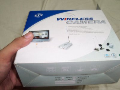
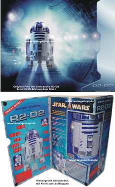
FIG01A -The wireless camera box
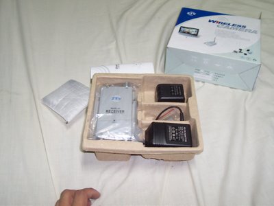
FIG01B -What the contents look like
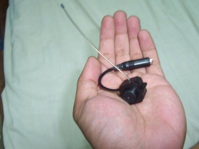
FIG02 -Closeup of the camera
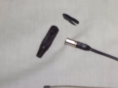
FIG03 -Removing unnecessary insulation (note that camera connector at right contains power regulating circuitry; DO NOT remove this)
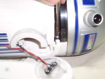
FIG04 -Removing Artoo's head (note the black double-sided adhesive tape)

FIG05 -Accessing Artoo's dome
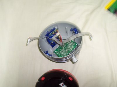
FIG06 -Main parts of Artoo's head (the black and red disks at the bottom of the picture are his neck and neck motor assembly)
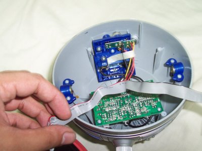
FIG07 -Interior of Artoo's dome

FIG08 -Dismantling eye sensor array
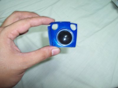
FIG09A -Artoo's non-functional eye (front view)
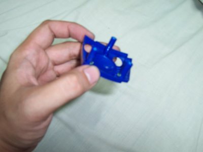
FIG09B -Artoo's non-functional eye (back view)
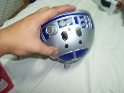
FIG10 -Artoo's dome without eye array

FIG11 -Melting Artoo's dome to make room for wireless camera

FIG12 -Finished dome modification
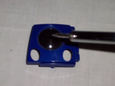
FIG13 -Melting Artoo's eye to make room for camera aperture

FIG14 -Completed modified eye after melting and fine sanding
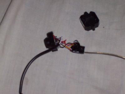
FIG15 -Dismantling camera to fit in Artoo's eye sensor array (note microphone and antenna sub-assemblies to the right)
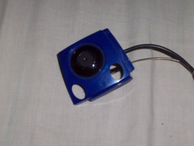
FIG16A -Eye fitted with camera (front view)
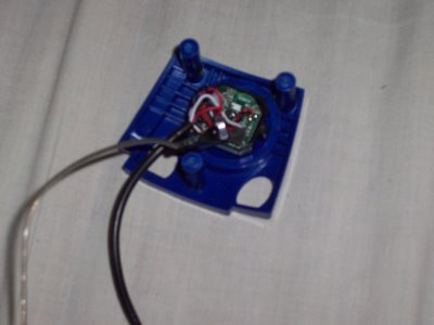
FIG16B -Eye fitted with camera (back view)
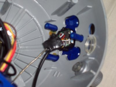
FIG17 -Dome fitted with camera and eye (note free-hanging microphone and antenna sub-assemblies)
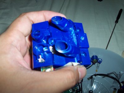
FIG18 -Filing of inner sensor array to further accommodate camera
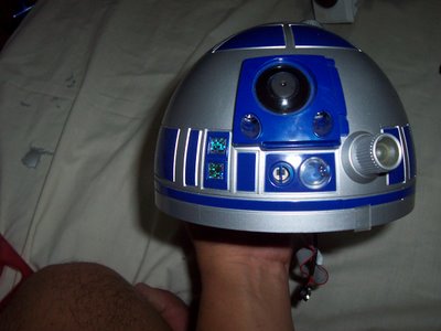
FIG19 -Finished modified Artoo dome (note Artoo's ribbon cables and as-yet unmodified camera battery leads at bottom of dome)
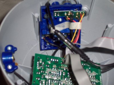
FIG20 -Connecting extension cable to camera's battery leads

FIG21 -Accessing Artoo's switch PCB
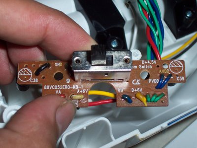
FIG22A -Closeup of switch PCB (note terminals marked GND and VA; the camera's negative and positive battery leads will be attached here, respectively)
FIG22B -Closeup of switch PCB (reverse side), prior to attaching positive camera lead; ground lead already attached
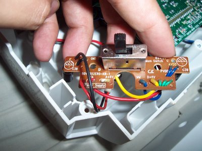
FIG23A -Closeup of switch PCB after attaching camera leads
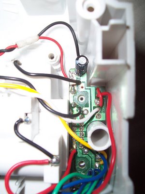
FIG23B -Closeup of switch PCB after attaching camera leads (reverse side)
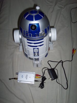
FIG24 -Modified Artoo with stock receiver

FIG25A -Jedi Commlink receiver housing head-on view
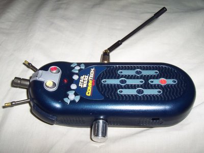
FIG25B -Jedi Commlink receiver housing side view (note the hole, visible in lower right of picture, to accommodate mains adapter)
© TJ Dimacali, 19July2006
posted by TJ Dimacali at 6:31 PM
![]()
![]()


13 Comments:
wow TJ!
nice work!!!!!!!!!!
hello
onboard model is ?
system operation c++ ??
is posible onboar sound blueetoth activaction talk by blueetoht ?
hello
onboard model is ?
system operation c++ ??
is posible onboar sound blueetoth activaction talk by blueetoht ?
Hello.
I have a interactive R2 with some problems. Can you help me? It stop to function after some minutes and his red light blink. Thks.
cambia las pilas... he leido en algun foro de ingleses ke las pilas dan bastantes problemas
Las pilas son nuevas.
Quizás abra el robot, a ver si tiene algún contacto mal.
¿Que foro? HE buscado ayuda técnica del bicho, y esto es lo más parecido... :-D
Gracias
hola daniel.
Yo aun no soy un afortundado como tu de poseer el r2-d2 :)
Estoy en espera de recibirlo esta semana o la otra comprado en ebay.
Del año 2005, pq se ve que los primeros que hicieron del 2001,2002 tuvieron problemas de sonido del micro y el detector de calor creo ke estaban o muy juntos o algun problema de calibraje...
En españa se venden si hay por 200 o mas euros... yo lo he conseguido por 120 euros, transporte incluido ke ya es una pasta. jejeje
Tengo ganas de tenerlo para manosearlo..
Lo de la camara me gusto eso de wirelesss..
Web ke hable del r2-de pues no creo ke haya ninguna.. como no la montes tu :)
:-D
No te digo lo que pagué por el mío, para que no te tires de los pelos. Pero es que lo compré a una tienda que lo tenían como estropeado, con la esperanza de arreglaro. a menos de la mitad de su coste. Si lo arreglo, bombazo. Si no... en fin. A ratos funciona.
Gracias, y un abrazo
aqui tienes la url del foro en ingles del r2-d2 http://forums.starwars.com/thread.jspa?threadID=87286&start=495
no habla espaniol!
nice work tj!
I don't understand. What is the point of the built-in camera? what does it accomplish? In other words, why would I want to modify my Hasbro R2 to do this?
What would be the benefit in entertainment or actual usage?
I would absolutely benefit from this installation guide.
tucson security systems
Your blog is very useful to all the people
wireless spy camera
mini spy cam
Post a Comment
<< Home